Kyoritsu 6010A User Manual
Browse online or download User Manual for Tools Kyoritsu 6010A. KYORITSU 6010A User Manual
- Page / 32
- Table of contents
- BOOKMARKS
- MULTI-FUNCTION TESTER 1
- CONTENTS 2
- 1. SAFE TESTING 3
- 2. FEATURES 5
- 3. SPECIFICATION 8
- 5. INSULATION TESTS 13
- 6. LOOP IMPEDANCE TESTS 19
- PHASES AT THE SAME TIME 21
- BLACK NEUTRAL 22
- RED PHASE 22
- GREEN EARTH 22
- 7. RCD TESTS 23
- 8. GENERAL 25
- 9. BATTERY REPLACEMENT 26
- 10. FUSE REPLACEMENT 26
- 11. SERVICING 27
- KYORITSU ELECTRICAL 32
- INSTRUMENTS 32
- WORKS, LTD. 32
Summary of Contents
MODEL6010AMULTI-FUNCTION TESTERINSTRUCTION MANUALKYORITSU ELECTRICAL INSTRUMENTS WORKS,LTD.
―8―is updated approximately five times per second.Overload protection The continuity test circuit is protected by a 0.5 A600 V fast acting(HRC)ceramic
―9―4. CONTINUITY(RESISTANCE)TESTSWARNINGENSURE THAT CIRCUITS TO BE TESTED ARE NOT LIVE.DISCONNECT THE INSTRUMENT FROM THE CIRCUIT UNDER TEST BEFORE OP
―10―4.3 Continuity testing1.Press the test button once. Then, the instrument switches on.2.Select the continuity test by rotating the function dial.3.
―11―5. INSULATION TESTSWARNINGENSURE THAT CIRCUITS TO BE TESTED ARE NOT LIVE.DISCONNECT THE INSTRUMENT FROM THE CIRCUIT UNDER TEST BEFORE OPERATING TH
―12―Fig 45.1.3 Conduction CurrentSince the insulation resistance is not infinite, a small leakage current flowsthrough the insulation between conducto
―13―5.1.5 Total Leakage CurrentThe total leakage current is the sum of the capacitive, conduction and surfaceleakage current described above. Each of
―14―¡ Electronic fluorescent starter switches¡ Passive infra-red detectors (PIRs)¡ Dimmer switches¡ Touch switches¡ Delay timers¡ Power controllers¡ E
―15―Fig 74.If the mains warning lamp lights and/or the buzzer sounds DO NOT PRESSTHE TEST BUTTON but disconnect the instrument from the circuit. Maket
―16―7.When testing is complete release the test button BEFORE disconnectingthe test leads from the circuit or from the appliance. This will ensure tha
―17―6. LOOP IMPEDANCE TESTSDISCONNECT THE INSTRUMENT FROM THE CIRCUIT UNDER TESTBEFORE OPERATING THE FUNCTION SWITCHTO SELECT THE LOOP TESTING RANGE S
1.Safe Testing... 12.Features...
―18―only be carried out after the mains supply has been connected. In many cases,any RCD in the circuit will be tripped by this test, which draws curr
―19―the reduced current of 15mA flowing.This setting will be very unlikely to tripout the circuit RCD.Note:Do not connect phase to phase as this inst
―20―Fig 9Fig 10BLACK NEUTRALRED PHASEGREEN EARTH
―21―7. RCD TESTSDISCONNECT THE INSTRUMENT FROM THE CIRCUIT UNDER TESTBEFORE OPERATING THE FUNCTION SWITCHTO SELECT THE RCD TEST RANGE SELECT“RCD”7.1 P
―22―10.Set the function switch to X1 for the“trip”test, which measures the timetaken for the RCD to trip with the set residual current.11.Set the &quo
―23―maximum of 2000ms on the X1/2 and X1 ranges. The fact that the RCDhas not tripped will be evident because the PN and PE LEDs will still beon.On RC
―24―9. BATTERY REPLACEMENTWhen the display shows the low battery indication, ( ), disconnect the testleads from the instrument. Remove the battery cov
―25―If this tester should fail to operate correctly, return it to your distributor statingthe exact nature of the fault. Before returning the instrume
―26―12.CASE, STRAP AND SHOULDER PAD ASSEMBLY Correct assembly is shown in Fig 12. By hanging the instrument round theneck, both hands will be left fre
―27―MEMO
―1―1. SAFE TESTINGElectricity is dangerous and can cause injury and death. Always treat it withthe greatest of respect and care. If you are not quite
―28―MEMO
―29―MEMO
00-0892-1455BDISTRIBUTORKYORITSU ELECTRICALINSTRUMENTSWORKS, LTD.No.5-20, Nakane 2―chome, Meguro-ku,Tokyo, 152-0031 JapanPhone:(03)3723―0131 Telex:024
―2―8.If abnormal conditions of any sort are noted (such as a faulty display,unexpected readings, broken case, cracked test leads, etc) do not use thet
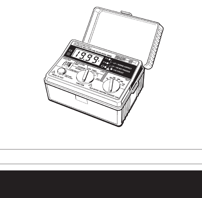
―3―2. FEATURESFUNCTION SWITCHTEST BUTTONRCD RATED TRIPPINGCURRENT SWITCHLIVE CIRCUIT LEDCONNECTORWIRING CHECKLEDLCD DISPLAYTest Lead with IEC Connecto
―4―Model 6010A Multi-Function tester performs five functions in one instrument.1.Continuity tester2.Insulation resistance tester3.Loop impedance teste
―5―Over temperature protection Detects overheating of the internal resistor(used for loop and RCD tests) and of thecurrent control MOS FET (used for R
―6―Open CircuitVoltage(DC)Short CircuitCurrentRange AccuracyGreater than 4VGreater than200mA20/200ΩAuto-RangingUp to 2ΩOver 2Ω±(3%rdg+4dgt) ±(3%rdg+3d
―7―To prevent wrong connection of test leads and to maintain safety, thededicated terminals used for continuity and insulation tests are automatically
More documents for Tools Kyoritsu 6010A

Related products and manuals for Tools Kyoritsu 6010A
 (28 pages)
 (36 pages)
(32 pages)
(32 pages)
(32 pages)
(33 pages)
(24 pages)
(1 pages)
(60 pages)
(28 pages)
(45 pages)
(36 pages)
(32 pages)
(32 pages)
(32 pages)
(33 pages)
(24 pages)
(1 pages)
(60 pages)
(28 pages)
(45 pages)
 (44 pages)
(1 pages)
(32 pages)
(44 pages)
(44 pages)
(1 pages)
(32 pages)
© 2020, manymanuals.com. All rights reserved. | 5.152 s |
 Manymanuals.com
 Manymanuals.de
 Manymanuals.fr
 Manymanuals.it
 Manymanuals.pl
 Manymanuals.cz
 Manymanuals.es
 Manymanuals-pt.com
Comments to this Manuals