on the fork shaped sensor.
3. Specification
AC current ∼A
DC current A
AC voltage ∼V
Note) NCV range is calibrated to detect the voltage, where non-grounded single wire,
AC80V or more. However, detecting sensitivity may be affected by the absence of
grounded or non-grounded metal tube or metal case. Also it may be affected in the
place where influenced by other voltages, how you grip the instrument or the
measuring position of sensor.
●CF(Crest Factor) CF=2.5 or less
●Standards IEC61010-1
Overvoltage CATIII 300V, pollution degree 2
IEC61010-2-032
IEC61326 (EMC standard)
●Indication LCD Max. 1049 units, symbols
●Over range display "OL" symbol is displayed on the LCD.
(Only on current range)
●Response time Approx. 2sec.
●Sampling rate Approx. twice per second
●Temperature &
Humidity range
(guaranteed accuracy) 23℃±5℃
Relative humidity: 75% or less (no condensation)
●Operating Temperature &
Humidity range 0 ∼ 40℃
Relative humidity: 85% or less (no condensation)
●Storage Temperature &
Humidity range -20 ∼ 60℃
Relative humidity: 85% or less (no condensation)
●Power source DC3V : R03(UM-4)x2pcs
●Current consumption Approx.12mA or less
To decrease current consumption, detecting circuit is on only
for 0.1/0.5sec.
●Power off function Power off function operates automatically after a switch
remains for 10min.
●Overload Protection AC/DC current : AC/DC 120A/ 10sec.
AC voltage (NCV) : AC360V/ 10sec.
●Withstand Voltage AC3700V/ for one min.
(Between electrical circuit and enclosures.)
●Insulation Resistance 10MΩ/1000V
(Between electrical circuit and enclosures.)
●Max. diameter of
measured object Max. 10mm
●Dimensions 161.3(L) x 40.2(W) x 30.3(D) mm
●Weight 110g(including batteries)
●Accessories Battery R03 --------------------- 2
Instruction manual ------------- 1
Carrying case ------------------- 1
Instruction Manual
1. Safety Warnings
This instrument has been designed and tested according to IEC Publication 61010:
Safety Requirements for Electronic Measuring Apparatus. This instruction manual
contains warnings and safety rules which must be observed by the user to ensure safe
operation of the instrument and to retain it in safe condition. Therefore, read through
these operating instructions before starting using the instrument.
WARNING
●Read through and understand instructions contained in this manual before starting
to use the instrument.
●Save and keep the manual handy to enable quick reference whenever necessary.
●Be sure to use the instrument only in its intended applications.
●Be sure to understand and follow all safety instructions contained in the manual.
Be sure to observe above instructions.
Failure to follow the above instructions may cause injury, instrument damage and/or damage to
equipment under test.
The symbol indicated on the instrument means that the user must refer to
related parts in the manual for safe operation of the instrument. Be sure to
carefully read the instructions following each symbol in this manual.
DANGER
is reserved for conditions and actions that are likely to cause serious or
fatal injury.
WARNING
is reserved for conditions and actions that can cause serious or fatal
injury.
CAUTION
is reserved for conditions and actions that can cause minor injury or
instrument damage.
DANGER
●Never make measurement on the circuit above AC/DC300V.
●Do not attempt to make measurement in the presence of flammable gasses. Otherwise,
the use of the instrument may cause sparking, which can lead to an explosion.
●Never attempt to use the instrument if its surface or your hand is wet.
●Do not exceed the maximum allowable input of any measurement range.
●Do not open the battery cover and the instrument case when making measurement.
WARNING
●Never attempt to make any measurement, if the instrument has any structural abnormality
noted, such as cracked case or exposed metal parts.
●Do not install substitute parts or make any modification to the instrument. Return the instrument
to Kyoritsu or your distributor for repair or re-calibration.
●Do not try to replace the batteries if the surface of the instrument is wet.
●Always switch off the instrument before opening the battery compartment cover for battery
replacement.
CAUTION
●Always make sure to check the function selector switch is set to the appropriate range before
starting measurement.
●Do not expose the instrument to the direct sun, high temperature and humidity or dewfall.
●Be sure to set the function selector switch to the "OFF" position after use. When the instrument
will not be in use for a long period, place it in storage after removing the batteries.
●Use a cloth dipped in water or neutral detergent for cleaning the instrument. Do not use
abrasives or solvents.
Reference
*Effective Value (RMS)
Most alternating currents and voltages are expressed in effective values, which are also referred
to as RMS (Root-Mean-Square) values. The effective value is the square root of the average of
square of alternating current or voltage values. Many clamp meters using a conventional
rectifying circuit have "RMS" scales for AC measurement. The scales are, however, actually
calibrated in terms of the effective value of a sine wave though the clamp meter is responding to
the average value. The calibration is done with a conversion factor of 1.111 for sine wave, which
is found by dividing the effective value by the average value. These instruments are therefore in
error if the input voltage or current has some other shape than sine wave.
*CF (Crest Factor) is found by dividing the peak value by the effective value.
Examples:
Sine wave: CF=1.414
Square wave with a 1: 4 duty ratio: CF=2
5. Preparation
(1) Check battery voltage
Set the Function selector switch to the position other than OFF position.
Battery Voltage is enough if indications are displayed clearly and "BATT" mark is not
displayed on the LCD. If "BATT" mark is indicated or no indication on the LCD, replace
batteries with new one according to battery replacement procedures shown in clause 8
in this document.
CAUTION
●Indications may not being displayed on the LCD despite the function selector switch
is at the position other than OFF position.
This is because power-off function operated automatically and the instrument turned off.
Power off function can be released by turning the function selector switch to OFF,
and then set it to the range on which you would like to make a measurement.
If LCD still blank, batteries are completely exhausted. Please replace batteries.
(2) Check the function selector switch is set to the appropriate range. And also check data
hold function is not enabled. If inappropriate range is selected, desired measurement
cannot be made.
6. Measurements
6-1 Current Measurement
DANGER
●To avoid getting an electrical shock, never make measurement on the circuit in
which electrical potential over AC/DC300V exists.
●Do not make measurement with battery cover removed.
CAUTION
●Max. diameter of measured object(conductor) is Φ10mm.
6-1-1 DC current measurement
(1) Set the function selector switch to " A" position.
(" " and "A" marks will be displayed on the LCD.)
(2) Press HOLD/0ADJ button for 2sec or more to enable 0ADJ function and adjust the
indication on the LCD to be 0.
(Indication shall be adjusted to 0. Otherwise, error occurs.)
(3) Place one measured conductor lower than the triangle mark indicated on the fork
shaped sensor and make a measurement. (shaded part in the figure)
Then measured value is displayed on the LCD.
(When the center of the conductor is not lower than the triangle mark indicated on the
fork shaped sensor, error occurs.)
Note) When current is flowing from the upside to the underside of the instrument, reading
is positive(+), on the contrary, reading to be negative(-) when current is flowing from
the underside to the upside of the instrument.
6-1-2 AC current measurement
(1) Set the function selector switch to "∼A" position.
("∼" and "A" marks will be displayed on the LCD.)
(2) Place one measured conductor lower than the triangle mark indicated on the fork
shaped sensor and make a measurement. (shaded part in the figure)
Then measured value is displayed on the LCD.
(When the center of the conductor is not lower than the triangle mark indicated on the
fork shaped sensor, error occurs.)
(1) 100V mode
Sensitivity on this mode is set sharp, therefore, the presence of AC voltage can be
checked only by placing the instrument closer to the measured object, such as an
outlet, a plug and parallel cords, as shown in figure.
(2) 200V mode
Sensitivity on this mode is set dull, so the earth side and non-earth side of 100V cable
way can de verified. (Where cables are crowded, such as in a distribution board, earth
side could not be verified.)
Also can check the presence of AC voltage in 200V cable way, plug, outlet, fuse and
circuit breaker.
7. Other functions
7-1 Auto power off function
This function causes the instrument to automatically enter the power-off mode about
10min after the last function selector switch operation.
To release the power-off function, turn off the instrument and then turn on again.
7-2 Data hold function (Only on ACA/DCA range)
This is a function to hold the measured value on the LCD. "H" mark is shown on the
LCD while the instrument is in the data hold mode. To exit the data hold mode, press
the data hold button again.
Note) The measured value being held will be released when auto power-off function
operates while data hold function is operating.
8. Battery replacement
WARNING
●To avoid getting electrical shock, be sure to set the function selector switch to
"OFF" position before trying to replace the batteries.
CAUTION
●Do not mix new and old batteries.
●Make sure to install battery in correct polarity as indicated inside the battery cover.
When "BATT" mark is shown on the upper left corner of the LCD, replace the batteries.
Note that the battery is completely exhausted, the LCD blanks without "BATT" mark
shown.
(1) Se the function selector switch to "OFF" position.
(2) Unscrew the battery cover fixing screws and remove the battery cover on the bottom of
the instrument. Then replace new batteries. (R03 x 2pcs)
Range
ACA
Measuring range
0∼100A
Accuracy
±2.0%rdg±5dgt(50/60Hz)
±3.0%rdg±5dgt(50/60Hz)
CF(Crest factor)
CF≦2
2<CF≦2.5
Range
DCA
Measuring range
0∼±100A
Accuracy
±2.0%rdg±5dgt
Range
NCV
Measuring range
AC300V or less
Action
Normal condition : Lo
At voltage detecting(single wire AC80V or more) : Hi
92
―
1556A03
―
03
KYORITSU ELECTRICAL INSTRUMENTS
WORKS, LTD.,
Note) For the measurement of AC current, zero adjustment, which is required for the
measurement of DC current, is not necessary. Current flowing direction has no
relation to the indication polarity.
6-2 Non contact voltage detection(NCV)
This function is to check the presence of voltage without touching wires or electrodes
directly.
Also can check the presence of AC voltage in cable, outlet, fuse and circuit breaker.
[Details]
While voltage is applied to a cable or outlet, the electric field depending on the voltage
is generated. This instrument detects the generated electric field, and verifies the
presence of AC voltage. Officially, it is called as an instrument for detecting electrical
field. But it is not a familiar term, so we call it as "Non contact voltage detection".
General detectors detect voltage by contacting polarized voltage(contacts and
terminals). But this instrument is developed to satisfy this function and for safety
purpose without contacting voltage.
DANGER
●To avoid getting an electrical shock, never make measurement on the circuit in
which electrical potential over AC/DC300V exists.
●Before a measurement, be sure to check the instrument operation with well-known
power supply. If "Err" is displayed on the LCD, do not make a measurement.
●Do not make measurement with battery cover removed.
●Indication on NCV range is a reference value. Make sure to check the voltage with a
precise equipment in advance when operator will directly touch or connect wires.
●Indication of voltage may be affected by non-grounded metal tube or metal case, the
place where affected by other voltages, handgrip or the measuring position of sensor.
6-2-1 Measurements
(1) Set the function selector switch to "NCV" position.
(2) The sensing mode (100V or 200V) in effect is displayed on the LCD for 1min, and NCV
measurement starts.
(3) Position the tip part of fork typed sensor against the measured object.
When voltage is detected, "Hi" will be displayed on the LCD.
(Error could occur depending on the direction, angle and contact surface of the
instrument against the measured object. On NCV range, data hold function cannot be
used.
)
Note) When set the function selector switch to NCV range, self-check function operates
and Indicates "Err", if there is some fault or abnormal condition. Do not make a
measurement if such indication displayed on the LCD.
6-2-2 Sensing mode
●There are two types of sensing mode: 100V mode and 200V mode.
●Above two modes can be changed over by pressing the data hold button 2sec or more.
(The selected sensing mode is stored even if switching off the instrument. When setting
the function switch to "NCV" again, measurement can be done on the same mode.)
●Factory setting : 200V mode
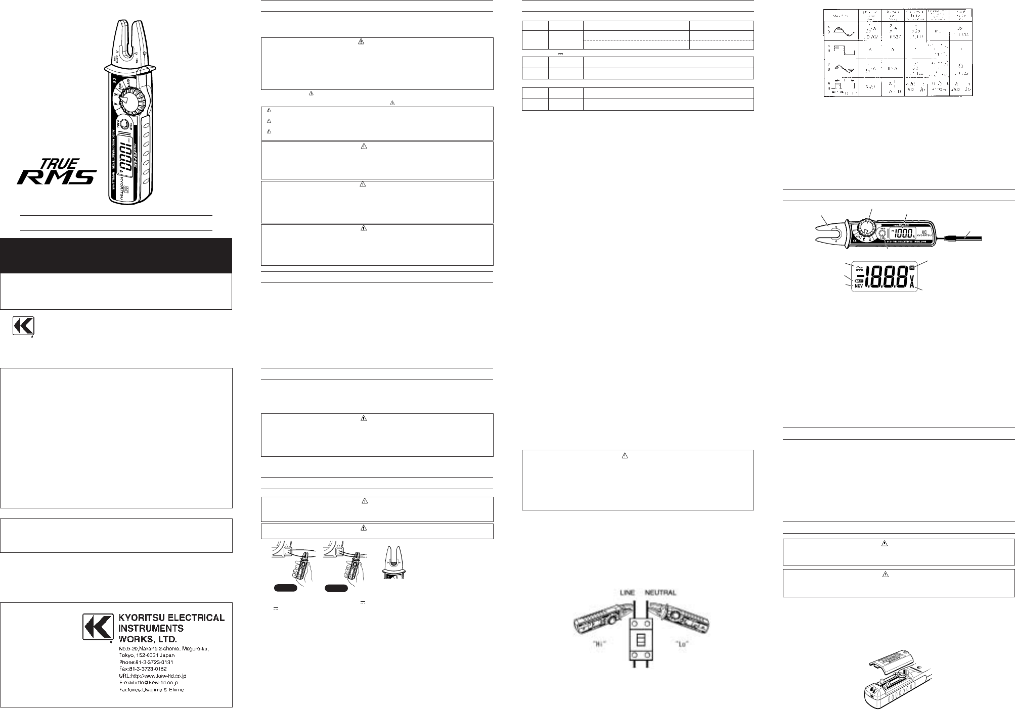
4. INSTRUMENT LAYOUT
DISTRIBUTOR
Kyoritsu reserves the rights to change specifications or
designs described in this manual without notice and without
obligations.
AC/DC FORK CURRENT TESTER
MODEL 2300R
KEW FORK
Co
rre
ct
Wrong
2. Features
●This instrument, Fork current tester, can measure AC/DC current up to 100A without
opening and closing the Jaws.
●True RMS reading for AC current
●Fork shaped sensor for easy measurement at tight places and crowded cable areas.
●NCV function (Non Contact Voltage) enables live wire check
●Auto power off function
●Data hold function
●Pocket size handy tester, adopted over-molding for a better fit
●Carrying case furnished as a standard accessory.
●Designed to international safety standards.
IEC 61010-2-032 overvoltage CAT.III 300V Pollution degree 2

 (1 pages)
 (8 pages)
 Manymanuals.com
 Manymanuals.de
 Manymanuals.fr
 Manymanuals.it
 Manymanuals.pl
 Manymanuals.cz
 Manymanuals.es
 Manymanuals-pt.com
Comments to this Manuals